Determining the blank length of bent metal components
- Swift Metal Services

- Jun 10, 2020
- 2 min read
Updated: Sep 14, 2020
Sheet metal forming processes are when we apply force to a piece of sheet metal to modify its geometry rather than remove any material. Metal bending is a forming process used by contract metal manufacturers. A force is applied to a sheet metal blank, therefore, causing it to bend at an angle and form a required shape. When a flat metal component is bent, the outside surface of the sheet will undergo tension and stretches to a greater length. The inside portion experiences compression and consequently will shorten in length. The boundary line inside the sheet metal, which is not affected by either tension or compression forces is known as the neutral axis. The length of this line remains constant. The location of the neutral axis varies according to the material grade and thickness. The K-factor is the ratio of the neutral axis offset (t) and the material thickness (MT)
KF = t/MT
The only accurate way to determine the K-factor is to bend a sample piece of steel and calculate the bend allowance. The bend allowance is the length of the neutral axis between the bend lines. Or the arc length of the bend. As a result, this figure tells us how much we need to add or remove to the leg lengths to determine the accurate blank size.
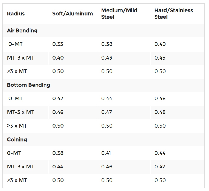
However, for general fabricated brackets and non-critical components, the figures in the below table can be used to determine the K-factor. Hence calculating the correct blank length of your metal components.

To use this table and calculate the Bend Allowance, use the formula below:
BA =π(R+KT) A/180
Where:
BA = Bend Allowance
R = Inside bend radius
K = K-factor (as above table)
T = Material thickness
A = Bend angle
Finally, you can now determine the correct length of the sheet metal blank by:
L = A + B + BA

Points to consider in the design of bent metal brackets and components:
The ideal inner radius should be at least equal to the material thickness of the part.
If possible, keep the bend radius consistent, to reduce extra set-up times & added cost.
The flange width should always be at least 4 x MT + bend radius. This helps to prevent distortion and also preserves the tooling quality.
Holes and slots should be at least 3 x MT + bend radius from the bend.


Comments